Category Archives: Industry

Industry

how to style a planetary gearbox?

Creating a planetary gearbox calls for cautious thing to consider of several aspects this sort of as torque necessities, pace ratios, efficiency, sizing constraints, and application-unique desires. Whilst a in depth style procedure involves comprehensive engineering calculations and issues, right here are the common measures included in developing a planetary gearbox:

one. Ascertain Necessities: Outline the prerequisites of the gearbox, which includes torque capacity, velocity ratios, input and output speeds, and any certain software constraints.

two. Gear Arrangement Choice: Select the acceptable equipment arrangement based on the necessities. Planetary gear units provide a variety of configurations, this sort of as uncomplicated China planetary gearbox exporter, compound planetary, or differential planetary. Look at aspects these kinds of as torque distribution, compactness, and effectiveness when deciding on the arrangement.

three. Gear Sizing: Decide the selection of teeth and module (tooth dimension) for each individual gear in the system. This consists of performing calculations and investigation to be certain satisfactory power, speak to ratios, and meshing traits. Contemplate equipment products, tooth profiles, and manufacturing limitations in the course of the sizing method.

four. Bearing Choice: Opt for suited bearings to aid the gears and China planetary gearbox shafts. Think about factors this kind of as load capacity, durability, and alignment demands. Proper bearing collection is crucial for sleek operation and longevity of the gearbox.

5. Shaft Design: Layout the enter and output shafts primarily based on the torque and pace specifications. Look at shaft substance, diameter, keyways, and coupling techniques to guarantee sufficient power and compatibility with the connected factors.

6. Housing Design: Design the gearbox housing to enclose and assist the gears and shafts. Take into consideration factors this kind of as structural integrity, accessibility for maintenance, sealing to avert lubricant leakage, and thermal administration.

seven. Lubrication Process: Build a lubrication method to make sure proper lubrication of the gears and bearings. Take into account oil viscosity, stream costs, cooling mechanisms, and filtration for successful operation and extended lifespan.

eight. Assessment and Optimization: Conduct engineering calculations, these kinds of as gear tooth worry analysis, contact ratio investigation, effectiveness calculations, and thermal investigation. Use simulation software package or accomplish hand calculations to consider the effectiveness and enhance the design and style for efficiency, toughness, and sound reduction.

9. Prototype and Screening: Create a prototype of the gearbox and carry out arduous tests to validate the structure. Measure effectiveness parameters this sort of as torque transmission, performance, sound concentrations, and durability under working problems. Analyze test facts and make vital style and design refinements.

10. Manufacturing and Assembly: As soon as the structure is finalized and validated, prepare comprehensive production drawings and technical specs. Coordinate with producers to make the gears, shafts, housing, and other elements. Assemble the gearbox with precision, ensuring proper alignment and lubrication.

It is really crucial to take note that developing a planetary gearbox calls for experience in mechanical engineering and information of equipment style and design principles. Consulting with professional professionals or making use of specialized application can significantly support in the layout procedure.
how to meg a motor?

“Megging” a motor refers to performing a megohmmeter take a look at, also identified as a megger test, on a motor. This check is utilized to evaluate the insulation resistance of the motor windings to detect any insulation breakdown or faults. This is a basic tutorial on how to meg a motor:

1. Safety safety measures: Make sure that the motor is wholly disconnected from the power supply and has been appropriately locked out and tagged out to protect against accidental energization throughout the check. Wear proper personal protecting gear (PPE) these kinds of as gloves and safety eyeglasses.

two. Attain a megohmmeter: A megohmmeter, or megger, is a specialised instrument utilized for insulation resistance screening. Make guaranteed you have access to a reliable and effectively calibrated megger suitable for motor tests.

3. Preparation: Clean up the motor factory terminals and be certain they are totally free from any dust, humidity, or contaminants that could impact the check benefits. Confirm that the motor windings are dry.

four. Link the megger: Join the sales opportunities of the megger to the motor terminals. The megger usually has a few potential customers: 1 for the good (+) terminal, 1 for the detrimental (-) terminal, and 1 for the guard terminal. Ensure proper connections according to the megger manufacturer’s guidance.

five. Pick the proper take a look at voltage: Established the megger to the ideal take a look at voltage for the motor becoming analyzed. The recommended take a look at voltage can range based on the motor’s voltage ranking, sizing, and insulation course. Refer to the motor’s technical specs or check with an skilled for the correct exam voltage.

six. Conduct the check: Activate the megger and make it possible for it to apply the check voltage throughout the motor windings. The megger will evaluate the insulation resistance in megohms (MΩ). The check duration can change, but it is ordinarily completed for a single minute. The megger will exhibit the insulation resistance worth.

7. Interpret the outcomes: motor factory Evaluate the measured insulation resistance value with the motor manufacturer’s requirements or regarded marketplace expectations to figure out if the motor’s insulation is in an appropriate vary. Reduced insulation resistance values may well reveal insulation deterioration or faults.

8. Doc and review the final results: Document the check benefits, which include the measured insulation resistance worth and any notes or observations. Compare the benefits to earlier examination data, if offered, to detect any important changes or developments.

If the megger take a look at reveals minimal insulation resistance or other indications of insulation breakdown, it is proposed to check with with a skilled electrician or motor expert for further analysis and vital repairs.

Observe: It truly is essential to abide by the distinct directions outlined in the megger’s user manual and adhere to all security recommendations whilst undertaking the megging check.

Link

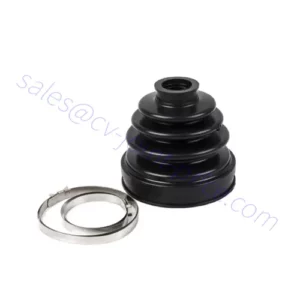
A failing or destroyed CV joint can be a critical challenge that ought to be tackled immediately. Here is why:

1. Safety Issues: A CV joint performs a vital function in transferring power from the transmission to the wheels while making it possible for for clean and regular ability delivery, even for the duration of turns. When a CV joint fails, it can guide to unpredictable managing, compromised steering command, and even sudden reduction of electrical power to the wheels. This can be notably unsafe in conditions that involve fast maneuvering or crisis stops.

two. Drivability Issues: A defective CV joint can trigger many drivability issues. It may outcome in vibrations, shuddering, or clunking noises while driving, especially during acceleration or when creating turns. These indications can negatively have an impact on the consolation, overall performance, and overall drivability of the vehicle.

3. Hurt to Other Factors: If a CV joint fails completely, it can induce even more harm to other factors of the drivetrain. For illustration, a damaged CV joint can hurt the axle shaft, wheel bearings, or differential. This can guide to more in depth and pricey repairs if left unaddressed.

4. Stranded on the Road: In some instances, a severely ruined China cv joint supplier joint can bring about a complete reduction of energy to the wheels, leaving you stranded on the street. This can be specifically problematic if it happens in an inconvenient or unsafe place.

Supplied these factors, addressing a CV joint issue as shortly as achievable is essential to guarantee protection, protect against even further hurt, and China cv joint supplier prevent possible breakdowns. If you suspect a problem with your CV joints, it is encouraged to have your vehicle inspected and repaired by a qualified mechanic or automotive technician. They can assess the condition of the CV joints, execute necessary repairs or replacements, and restore the suitable functioning of your motor vehicle.

how does a rack and pinion gear work?

A rack and pinion equipment system is a variety of mechanical system utilised to transform rotational motion into linear movement. It is composed of a straight toothed rack (a flat bar with teeth alongside its length) and a pinion equipment (a compact equipment with teeth). This is how the rack and pinion equipment works:
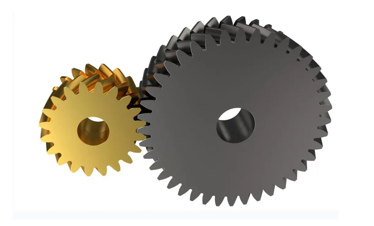
1. Rack: The rack is a straight bar with evenly spaced teeth together its length. It functions as a linear equipment and supplies a straight path for motion. The enamel on the rack mesh with the teeth on the pinion gear.

two. Pinion Gear: The pinion equipment is a small gear with enamel that mesh with the tooth on the rack. It is commonly attached to a rotary enter, these as a steering wheel in the circumstance of a car’s steering technique. The pinion equipment rotates when the enter is turned.

3. Meshing of Tooth: As the pinion China gear rack supplier rotates, its enamel interact with the enamel on the rack, causing the rack to move linearly in reaction to the rotation of the pinion gear. The rotation of the pinion equipment converts into linear motion of the rack.

4. Route of Motion: China gear rack manufacturer The path of linear movement of the rack is dependent on the orientation of the pinion gear. If the pinion equipment is oriented vertically, the rack will shift up and down. If the pinion equipment is oriented horizontally, the rack will move left and suitable.

5. Mechanical Edge: The rack and pinion equipment procedure is designed to deliver mechanical gain. Mainly because the pinion gear is smaller than the rack, every single rotation of the pinion gear outcomes in a larger linear displacement of the rack. This gives a mechanical benefit, making it possible for for exact and efficient movement conversion.

Apps of Rack and Pinion Gear:

– Steering program in automobiles: Rack and pinion gears are frequently utilized in the steering techniques of cars, trucks, and other motor vehicles. When the driver turns the steering wheel, it rotates the pinion equipment, which moves the rack, therefore steering the wheels.

– Linear actuators: Rack and pinion gears are employed in numerous linear movement apps, these as in industrial machinery and automation units. The rotational input is applied to create linear motion for duties like opening and closing doorways, going platforms, or controlling robotic arms.

The simplicity and effectiveness of rack and pinion equipment methods make them widely utilized in different mechanical applications wherever converting rotational motion into linear movement is expected.

how to design and style plastic injection molded components

Planning plastic China Injection molded parts exporter molded sections involves various considerations to make sure productive and China Injection molded parts effective manufacturing. In this article are some measures to manual you through the procedure:

1. Determine Needs: Clearly set up the useful and overall performance requirements for the component. Think about things such as aspect geometry, content assortment, mechanical attributes, China Injection molded parts dimensional tolerances, floor end, and any precise sector requirements or polices.

2. Content Choice: Pick a ideal thermoplastic material for injection molding dependent on your prerequisites. Contemplate components such as mechanical homes, chemical resistance, temperature resistance, price tag, and availability. Seek the advice of materials datasheets and collaborate with substance suppliers to make an knowledgeable choice.

3. Element Geometry: Layout the section geometry with thing to consider for moldability, operation, and aesthetics. Retain uniform wall thickness anywhere doable to guarantee proper movement of molten plastic in the course of injection molding. Integrate capabilities such as draft angles, ribs, bosses, and fillets as required.

four. Draft Angles: Integrate draft angles (tapered surfaces) into the section style to facilitate simple aspect ejection from the mould and steer clear of undercuts. Adequate draft angles normally array from .five to two levels, dependent on the product and element size.

five. Wall Thickness: Retain dependable and proper wall thickness in the course of the element style. Varying wall thickness can lead to uneven cooling, warping, or sink marks. Goal for a wall thickness concerning one-5 mm, based on the section measurement and substance.

6. Gate Placement: Determine acceptable gate areas for the injection of molten plastic into the mold cavity. Gate placement affects the filling pattern, aspect visual appeal, China Injection molded parts exporter and material stream. Widespread gate styles incorporate edge gates, pin-level gates, or sub-gates. Stay clear of inserting gates on significant surfaces or spots necessitating a high beauty finish.

seven. Ribs and Fillets: Incorporate ribs to raise section stiffness while minimizing materials usage. Use fillets or rounded corners to lower worry focus and aid product stream for the duration of molding. Preserve acceptable thickness and height ratios in between ribs and adjacent partitions to prevent sink marks or warpage.

8. Parting Line: Establish the parting line, which is the separation line concerning mold halves, and make certain it does not interfere with crucial surfaces or functions. Style and design the parting line to let for right mold opening and component ejection.

nine. Undercuts and Facet Actions: Lessen or get rid of undercuts and side actions in the part style and design, as they complicate mold design and style and maximize producing costs. If undercuts or facet actions are important, plan for further mildew capabilities like slides or lifters to accommodate them.

ten. Floor Complete and Texture: Specify the preferred surface area end and texture for the element. Consider beauty prerequisites, practical desires (such as grip or slip resistance), and the abilities of the decided on mildew and material.

eleven. Layout for Production and Assembly: Consider ease of producing and assembly during the style process. Reduce the amount of factors, use snap-in good shape or interlocking options wherever appropriate, and assure correct alignment and suit concerning mating components.

twelve. Prototyping and Tests: Build prototypes or 3D-printed styles to examine the style, in good shape, performance, and effectiveness of the injection molded aspect. Carry out screening to validate the style versus the defined necessities.

Collaborating with skilled mildew designers and suppliers is extremely encouraged all through the layout course of action to optimize the aspect style and design for thriving injection molding. They can give important insights, offer layout comments, and assist address prospective production troubles. On top of that, making use of mold movement simulation software program can aid detect and solve opportunity troubles right before shifting forward with production.

what does a generate shaft do?

A push shaft, also identified as a propeller shaft or prop shaft, is a mechanical part employed in cars to transmit torque from the motor to the wheels. It plays a critical position in transferring ability and rotational motion from the vehicle’s electricity resource (engine or motor) to the wheels, enabling the automobile to shift.

Right here are the most important features and tasks of a push shaft:

1. Torque transmission: The principal goal of a push shaft is to transmit torque, or rotational pressure, from the engine or motor to the wheels. As the motor generates energy, it sends rotational motion by way of the transmission or transfer case, which is then transferred to the push shaft. The push shaft carries this rotational force and delivers it to the differential, which further more distributes the energy to the wheels.

two. Connecting differentials and axles: In automobiles with rear-wheel drive, four-wheel generate, or all-wheel China drive shaft methods, the generate shaft connects the transmission or transfer case to the differential(s). The differential, in turn, splits the torque amongst the wheels, enabling them to rotate at distinct speeds during cornering while sustaining traction and steadiness.

3. Accommodating suspension movement: The travel shaft need to be made to accommodate the motion and vacation of the vehicle’s suspension system. As the wheels shift up and down due to bumps, uneven surfaces, or suspension articulation, the generate shaft requires to flex or modify its size to prevent binding or injury. Universal joints or CV joints (Frequent Velocity joints) are usually integrated into the travel shaft to allow for for these actions although sustaining a constant rotational link.

4. Protecting equilibrium: Push shafts need to have to be well balanced thoroughly to reduce vibrations and be certain easy procedure. Imbalances in the travel shaft can induce unwanted vibrations, main to pain, greater have on on components, and prospective drivetrain troubles. Balancing strategies, these as the addition of counterweights or precision producing processes, are employed to realize a balanced push shaft.

General, the generate shaft serves as a important url in the drivetrain program, enabling the transfer of electricity from the motor or motor to the wheels. It plays a essential position in automobile propulsion and is designed to stand up to the torque, rotational forces, and movement needed for effective and responsible operation.

Why helical gears are silent?

China helical reducer exporter gears are recognized for their reasonably peaceful procedure when compared to some other kinds of gears. The key reason for their quieter operation is the gradual engagement and disengagement of the tooth through rotation. This is why helical gears are likely to be silent:

one. Angled Teeth: Helical gears have tooth that are reduce at an angle to the equipment axis, forming a helix condition. This angle results in the teeth to engage steadily as they arrive into call, relatively than earning instantaneous call like spur gears. The gradual engagement aids to reduce impact forces and lower noise technology.

2. Smoother Tooth Get hold of: The angled teeth of helical gears let for larger sized speak to regions in between the tooth compared to spur gears. This more substantial get hold of spot spreads the load above several tooth, ensuing in a extra even distribution of forces. As a consequence, the tooth working experience diminished localized tension and fewer noise-causing vibration during procedure.

3. Load Sharing: The helical tooth profile allows numerous teeth to be in contact simultaneously while transmitting electricity. This load-sharing characteristic allows distribute the load throughout a number of teeth, reducing the pressure on particular person tooth and reducing sound technology.

four. Lessened Backlash: The helical gear style inherently minimizes backlash, which is the slight hole involving the mating enamel when there is no load applied. Backlash can direct to noise and vibration through equipment procedure. The angled enamel of helical gears develop a self-aligning impact that aids cut down backlash, resulting in quieter procedure.

five. Lubrication: Good lubrication is critical for the silent and sleek operation of helical gears. Superior-high quality lubricants aid lower friction concerning the tooth surfaces, dampen vibrations, and dissipate heat. Suitable lubrication minimizes have on, sounds, and will increase the general performance of the equipment program.

Although helical gears offer you quieter procedure when compared to some other gear kinds, it’s significant to be aware that other variables, such as equipment excellent, appropriate alignment, and maintenance practices, also add to the total sound degree of a gear process.

Can you travel with lousy CV joint?

It is not advised to push with a negative CV joint. Though it may possibly be attainable to drive for a limited distance with a failing CV joint, executing so can lead to even more destruction and cv joint factory potentially unsafe situations. Here is why:

one. Security Problems: A undesirable CV joint can compromise the handling and control of your automobile. It may possibly bring about unpredictable steering actions, vibrations, or even a unexpected loss of power to the wheels. These troubles can make it difficult to manage management around the motor vehicle, primarily for the duration of turns or emergency maneuvers, growing the possibility of incidents.

2. Increased Injury Risk: Ignoring a lousy CV joint and continuing to generate can lead to further destruction to other parts of the drivetrain. A failing CV joint can lead to the destruction of the axle shaft, wheel bearings, or differential. The resulting harm can be more intensive and highly-priced to restore compared to addressing the challenge when it is initially identified.

three. Stranded on the Road: If a China cv joint manufacturer joint fails totally although driving, it can consequence in a reduction of electrical power to the wheels, leaving you stranded on the road. This can occur at an inconvenient or unsafe place, potentially necessitating a tow truck or roadside help to solve the circumstance.

Offered these dangers, it is a good idea to have a car or truck with a terrible CV joint inspected and fixed by a certified mechanic as shortly as achievable. They can assess the affliction of the CV joint, establish the extent of the problems, and advise the needed repairs or replacements. By having prompt motion, you can make sure the basic safety of yourself and some others on the highway and China cv joint manufacturer prevent even further destruction to your car or truck.

what is a twin clutch gearbox

A twin-clutch gearbox, also known as a dual-clutch transmission (DCT) or China gearbox distributor immediate-shift gearbox, is a form of automatic handbook transmission that combines the efficiency and rapid gear improvements of a manual transmission with the usefulness of an automatic transmission. It utilizes two different clutches and a number of sets of gears to permit seamless and speedy equipment shifting.

This is how a twin-clutch gearbox functions:

1. Dual Clutches: A dual-clutch China gearbox is composed of two different clutches—one for odd-numbered gears (one, 3, 5, etc.) and yet another for even-numbered gears (2, 4, 6, etc.). Each and every clutch operates independently and is dependable for partaking and disengaging its corresponding established of gears.

2. Equipment Pre-variety: China gearbox exporter Whilst driving in a specific equipment, the dual-clutch gearbox pre-selects the following gear that is probable to be wanted primarily based on things these kinds of as motor vehicle speed, motor load, and driver enter. This pre-assortment takes place in the qualifications, making ready the program for an instantaneous equipment adjust.

3. Seamless Gear Variations: When a equipment change is required, the twin-clutch gearbox engages the clutch of the existing gear although at the same time disengaging the clutch of the next gear. This allows for a just about uninterrupted transfer of energy amongst the motor and the gearbox, ensuing in sleek and swift equipment variations.

4. Gear Synchronization: In advance of participating the future equipment, the twin-clutch gearbox synchronizes the rotational speeds of the corresponding gears to guarantee a seamless changeover. This synchronization process occurs quickly and proficiently, enabling lightning-rapid equipment adjustments devoid of the have to have for a clutch pedal.

5. Constant Electrical power Delivery: With the two clutches and pre-picked gears, a dual-clutch gearbox can seamlessly change between gears devoid of any obvious interruption in electric power delivery. This lets for quick acceleration and successful shifting, enhancing both efficiency and gasoline performance.

Dual-clutch gearboxes are recognised for their rapid and exact equipment modifications, creating them well-known in large-general performance and sporting activities automobiles. They deliver the advantage of an automated transmission when supplying the direct and participating driving knowledge of a manual transmission. In addition, twin-clutch gearboxes can frequently be operated in completely computerized manner or handbook mode, offering drivers the versatility to choose their favored driving type.

What are the a few styles of coupling?

There are quite a few kinds of couplings employed in mechanical units, but a few frequently identified kinds are:

1. Adaptable Couplings: Flexible couplings are built to accommodate misalignments among the linked shafts even though transmitting electric power efficiently. They deliver versatility and China coupling distributor enable for angular, parallel, or axial misalignments. Some popular forms of flexible couplings consist of:

a. Gear Couplings: Gear couplings consist of interlocking enamel on the China coupling distributor halves, enabling torque transmission although accommodating angular misalignment.

b. Jaw Couplings: Jaw couplings have elastomeric spider inserts among the hubs, providing overall flexibility and dampening vibrations.

c. Lovejoy Couplings: Lovejoy couplings use a adaptable elastomeric factor, these kinds of as a rubber or polyurethane spider, to transmit torque while enabling for angular and parallel misalignments.

two. Rigid Couplings: Rigid couplings are applied when exact alignment between shafts is crucial, and no misalignment is predicted. They give a solid and rigid relationship, making sure correct torque transmission. Rigid couplings incorporate:

a. Sleeve or Muff Couplings: Sleeve couplings are uncomplicated cylindrical sleeves that connect two shafts. They rely on a limited in shape and keyway to transmit torque without having any flexibility.

b. Clamp or Break up Couplings: Clamp couplings consist of two halves with screws or clamps that tightly protected the coupling around the shafts, producing a rigid relationship.

c. Flanged Couplings: Flanged couplings have flanges on just about every shaft stop, and they are bolted collectively to produce a rigid link.

three. Fluid Couplings: Fluid couplings use hydraulic ideas to transmit ability amongst shafts. They present a smooth get started-up and torque transmission, dampening shock masses and torsional vibrations. Fluid couplings are usually utilized in apps exactly where superior torque is necessary, these types of as in heavy equipment or automotive transmissions.

a. Hydrodynamic Couplings: Hydrodynamic couplings use a fluid-loaded chamber to transmit torque. They consist of an impeller (related to the driving shaft), a turbine (linked to the driven shaft), and a fluid medium that transfers torque from the impeller to the turbine.

b. Torque Converters: Torque converters are a type of fluid coupling employed in automotive applications. They make the most of a blend of impeller, turbine, and stator to multiply torque and let for a variable speed ratio.

These are just a several examples of the various types of couplings accessible. Each sort of coupling has its very own pros and is ideal for specific purposes dependent on elements this kind of as torque demands, misalignment allowances, China coupling distributor working situations, and program dynamics.